Sheath Materials, Thermowells, Fittings And Terminations
SHEATH MATERIALS, THERMOWELLS, FITTINGS AND TERMINATIONS
SHEATH MATERIALS, THERMOWELLS, FITTINGS AND TERMINATIONS
Temperature sensor elements for laboratory and industrial use, whether Pt100 or thermocouple will normally be protected by some form of sheath or housing. A wide range of installation fittings and accessories is available to facilitate installation in the actual process and to permit convenient interconnection with instrumentation.
Construction Of Industrial Temperature Probe
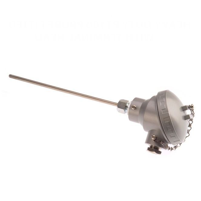
Fig 21: Industrial Temperature Probe
The assembly illustrated will be externally identical for both Pt100 or thermocouple sensors.
The protection tube (or sheath) houses the thermocouple or Pt100 either directly or indirectly via an insert. Additionally, a thermowell may be utilised for purposes of installing the probe into the process or application.
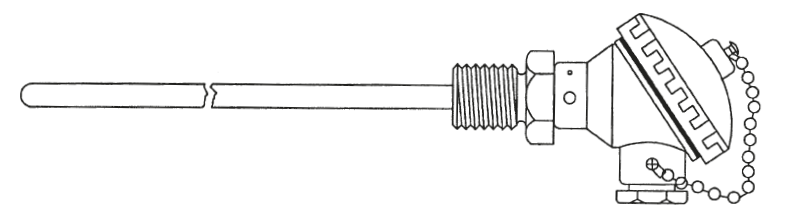
Fig 22: Industrial Temperature Probe with Thread Fitted below the Head
Sensor inserts are fabricated units which comprise a sensor and terminal base; the sensor is housed in a stainless steel insert tube, usually of 6 or 8mm diameter and this is inserted into the actual protection tube. Good seating with physical contact between the insert tip and sheath end is essential to ensure good heat transfer. Spring contact is used in the terminal base to maintain this contact. This arrangement facilitates easy replacement of this sensor as necessary.
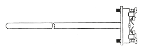
Fig 23a: Sensor Insert
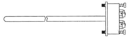
Fig 23b: Sensor Insert with Fitted Transmitter
In the case of a mineral insulated thermocouple or Pt100, the sensor is integral with the insert tube.
When a sensor insert is not specified, the sensor is housed directly in the probe and a suitable insulant is used to achieve electrical and/or thermal isolation from the sheath wall as required. Replacement requires exchanging the entire assembly in this case. A temperature transmitter can be fitted to the terminal base to provide a complete sensor and signal conditioning insert.
A thermowell or pocket can be used to facilitate sensor replacement without disturbance to the process. Fitted permanently into the process via a thread or flange, the thermowell also provides protection for the probe against aggressive media as well as maintaining physical process integrity in the event of probe removal.
The use of a thermowell does impair thermal response to some extent and does not provide a good approach if fast response to temperature changes is required.
Many alternative types of terminal head are available to meet the requirements of various applications. Variations exist in size, material, accommodation, resistance to media, resistance to fire or even explosion and in other parameters. Common types are shown below but there are many special variants available to meet particular requirements.
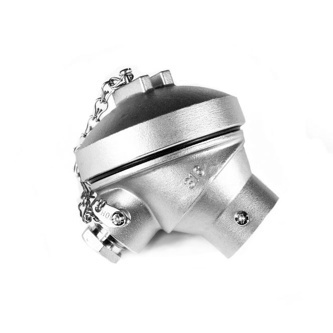
Fig 24: Terminal Head
DIN standard 43 729 defines two such types of head which dominate the European market. Identified as Types A and B. The smaller Type B version, is the most popular and 2 wire transmitters are usually designed to fit inside the DIN B head. Terminal block located in a “head” allow for the connection of extension wires. Various materials are used for screw or solder terminations including copper, plated brass and, for the best performance in the case of thermocouples, thermoelement alloys.
The various head styles cater for a wide variety of probe diameters and cable entries.
Alternatives to terminal heads include extension leads directly exiting probes, plug and socket connections fitted to probes and “tails” (short connecting wires). Cost savings can be thus realised when a head is not required although overall ruggedness may be limited to some extent especially when a direct extension lead is specified. Robust cable types are available.
Sheath materials range from mild and stainless steels to refractory oxides (ceramics, so called) and a variety of exotic materials including rare metals. The choice of sheath must take account of operating temperature, media characteristics, durability and other considerations including the material relationship to the type of sensor.
The application guide below provides details of various commonly specified sheath materials.
Thermocouple Sheath Materials – Application Guide
|
Sheath Material |
Maximum Continuous Temperature |
Notes |
Applications |
|
Refractory Oxide recrystallised, e.g. Alumina Impervious |
1750°C
|
Good choice for rare metal thermocouples. Good resistance to chemical attack. Mechanically strong but severe thermal shock should be avoided.
|
Forging iron & steel. Incinerators carburizing and hardening in heat treatment. Continuous furnaces. Glass Lehrs.
|
|
Silicon Carbide (Porous) |
1500°C
|
Good level of protection even in severe conditions. Good resistance to reasonable levels of thermal shock. Mechanically strong when thick wall is specified but becomes brittle when aged. Unsuitable for oxidising atmospheres but resists fluxes.
|
Forging iron & steel. Incinerators Billet heating, slab heating, Butt welding. Soaking pits ceramic dryers.
|
|
Impervious Mullite |
1600°C |
Good choice for rare metal thermocouples under severe conditions.Resists Sulphurous andcarbonaceous atmospheres. Good resistance to thermal shock should be avoided.
|
Forging iron & steel.Incinerators. Heat treatment. Glass flues.Continuous furnaces.
|
|
Mild Steel (cold drawn seamless)
|
1150°C
|
Resists corrosion even atelevated temperature.Can be used in Sulphurous atmospheres.
|
Heat treatment annealing, flues, manychemical processes. Vitreous enamelling. Corrosion resistant alternative to mild steel.
|
|
Inconel 600/800* |
1200°C
|
Nickel-Chromium-Ironalloy which extends theproperties of stainlesssteel 25/20 to higher operating temperatures. Excellent in Sulphur freeatmospheres; superiorcorrosion resistance athigher temperatures. Good mechanical strength.
|
Annealing, carburizing,hardening. Iron and steelhot blast. Open hearthflue & stack. Waste heatboilers. Billet heating, slabheating. Continuous furnaces. Soaking pits. Cement exit flues & kilns.Vitreous enamelling. Glass flues and checkers.Gas superheaters. Incinerators up to 1000°C. Highly sulphurous atmospheresshould be avoided above 800°C.
|
|
Chrome Iron
|
1100°C
|
Suitable for very adverseenvironments. Good mechanical strength. Resists severely corrosiveand sulphurous atmospheres.
|
Annealing, carburizing,hardening. Iron & steelhot blast. Open hearthflue and stack. Waste heat boilers. Billet heating, slab heating. Continuous furnaces. Soaking pits, Cement exit flues & kilns, Vitreous enamelling, Glass flues and checkers. Gas superheaters. Incinerators up to 1000°C.
|
|
Nicrobell*
|
1300°C
|
Highly stable in vacuumand oxidising atmospheres. Corrosionresistance generally superior to stainless steels. Can be used in Sulphurous atmospheresat reduced temperatures.High operating temperature.
|
As Inconel plus excellentchoice for vacuum furnaces and flues.
|
* Tradenames
Metallic and Non-Metallic Sheath Materials
The choice of metallic or non-metallic sheathing is mainly a function of the process temperature and process atmosphere. Ceramic (non-metallic) tubes are fragile but have a high chemical resistance; they can withstand high temperatures (up to 1800°C in some cases). Metallic tubes, most commonly stainless steels, have mechanical advantages and higher thermal conductivity; they are also generally immune to thermal shock which can easily result in the shattering of ceramic tubes. Depending on the alloy specified, metallic sheaths can be used at temperatures up to 1150°C (higher in the case of rare metals such as Platinum or Rhodium). Ceramics are superior when high purity is required to avoid sensor or product contamination at elevated temperatures (outgassing is minimal or non-existent)
Metallised ceramic tubes are available which endow the ceramic material with greater mechanical strength and surface hardness. Although ceramic based tubes generally display high electrical insulation, some types can become electrically conductive at elevated temperatures. They must therefore not be relied upon for electrical insulation under all conditions.
The temperature sensor and associated connecting wires must be electrically insulated from each other and from the sheath except when a grounded (earthed) thermoelement is specified. Such insulation can take various forms including mineral insulation, wires sleeved in suitable coverings such as glassfibre and ceramic insulators.
Ceramic Sheaths with thermocouple elements
Ceramic tubes, with their comparatively poor mechanical properties, are used when conditions exclude the use of metal, either for chemical reasons or because of excessive temperatures. Their main applications are ranges between 1000 and 1800°C. They may be in direct contact with the medium or may be used as a gastight inner sheath to separate the thermocouple from the actual metal protection tube. They should be mounted in a hanging position above 1200°C to prevent distortion or fracture due to bending stresses. Even hair-line cracks can lead to contamination of the thermocouple resulting in drift or failure. The resistance of the ceramic to temperature shock increases with its thermal conductivity and its tensile Highly stable in vacuum and oxidising atmospheres. Corrosion resistance generally superior to stainless steels. Can be used in Sulphurous atmospheres at reduced temperatures. High operating temperature. As Inconel plus excellent choice for vacuum furnaces and flues. strength and is greater for a smaller thermal expansion coefficient. The wall thickness of the material is also important; thin-walled tubes are preferable to larger wall thicknesses.
Cracks are frequently produced by subjecting the protection tubes to excessively rapid temperature changes when they are quickly removed from a hot furnace. The use of an inner and outer sheath of gas-tight ceramic is therefore advisable. The outer thin walled tube protects the inner one against temperature shock through the air between them. This lengthens the life of the assembly but results in slower response.
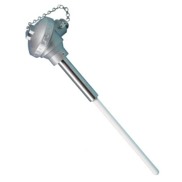
Fig 25: Rare Metal Thermocouple
In the case of rare metal thermocouples the ceramic has to be of very high purity. Platinum thermocouples are very sensitive to contamination by foreign atoms. Special care must therefore be taken with fittings for high-temperature measurements to ensure that insulation and protection tube materials are of high purity. Platinum wire must be handled with great care to avoid contamination; grease and metallic contaminants will present a threat at elevated temperatures. Many refractory materials including Aluminium Oxide (Alumina) and Magnesium Oxide (used as an insulant) become electrically conductive at temperatures above 1000°C. The use of high purity materials results in better insulation at elevated temperatures; multi-bore insulators in high grade recrystallised Alumina provide the best solution for thermoelement sleeving. The insulation behaviour of ceramics mainly depends upon their alkali content; the higher the alkali content, the higher the electrical conductivity becomes at even lower temperatures (800°C plus). Ceramics of pure Alumina display the best properties.
Thermowells provide protection for temperature probes against unfavourable operating conditions such as corrosive media, physical impact (e.g. clinker in furnaces) and high pressure gas or liquid. Their use also permits quick and easy probe interchanging without the need to “open-up” the process.
Thermowells take many different forms and utilise a variety of materials (usually stainless steels); there is a wide variety of thread or flange fittings depending on the requirements of the installation. They can either be drilled from solid material for the highest pressure integrity or they can take the form of a “thermopocket” fabricated from tubing and hexagonal bushes or flanges; the latter construction allows for longer immersion lengths.
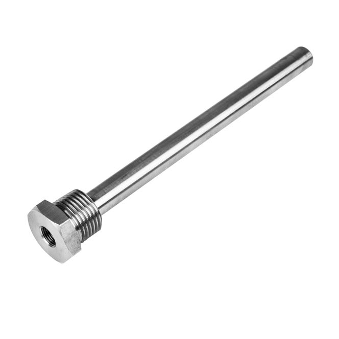
Fig 26: Threaded Thermowell
Thermowells transfer heat from the process to the installed sensor but “thermal inertia” is introduced. Any temperature change in the process will take longer to affect the sensor than if the thermowell were absent; sensor response times are thus increased. This factor must be considered when specifying a thermowell; except when thermal equilibrium exists, a temperature measurement will probably be inaccurate to some extent.
Optimum bore is an important parameter since physical contact between the inner wall of the thermowell and the probe is essential for thermal coupling. In the case of a thermocouple which is tip sensing it is important to ensure that the probe is fully seated (in contact with the tip of the thermowell). For Pt100 sensors which are stem sensing the difference between the probe outside diameter and bore must be kept to an absolute minimum.
Response times can be optimised by means of a tapered or stepped-down well which presents a lower thermal mass near the probe tip.
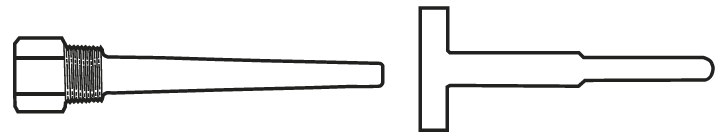
Fig 27: Tapered and Reduced Tip Diameter Well
Process connections are usually threaded or flanged but thermowells can be welded into position.
a) Threaded connections
Parallel or tapered (gas tight) threads make for convenient installation into a welded-in fitting directly into the process. Such a connection is suitable for smaller diameter wells which are not likely to be changed frequently (e.g. where corrosion rates are low). A hexagon is used at the top of the well for ease of fitting.
An extended hexagon length can be used to allow for insulation thickness. Typical thread sizes are
1/8” BSP (T), 1/2” BSP (T) or 20mm.
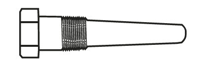
Fig 28: Tapered Thread Well
b) Flanged Connections
Flanged connections are preferable if there is a need for more frequent well replacement such as high corrosion rates. The flange bolts to a mating flange mounted on the process. Such a technique is more appropriate for large pipe diameters and for high pressure applications. Flanges are usually of 2 to 3 inches in diameter.
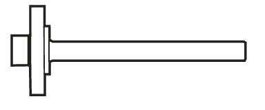
Fig 29: Flanged Parallel Well
c) Welded Connections.
Welded connections can be used when the process is not corrosive and routine removal is not required. High integrity is achieved and this technique is suitable for high temperature and high pressure applications such as steam lines. Removal of a welded-in well usually involves considerable effort and time.
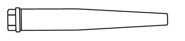
Fig 30: Weld-in Well
Lagging extensions are provided on thermowells (or even directly on probe assemblies) for use on lagged processes. A lagging extension distances the terminal head from the immersion part of the assembly to allow for the depth of lagging (thermal insulation). This technique is useful in allowing the head, perhaps with an integral transmitter, to reside in a cooler ambient temperature region rather than adjacent to the much hotter process.
Lagging extensions take various forms depending on overall probe or well construction, fitting method and type of termination.
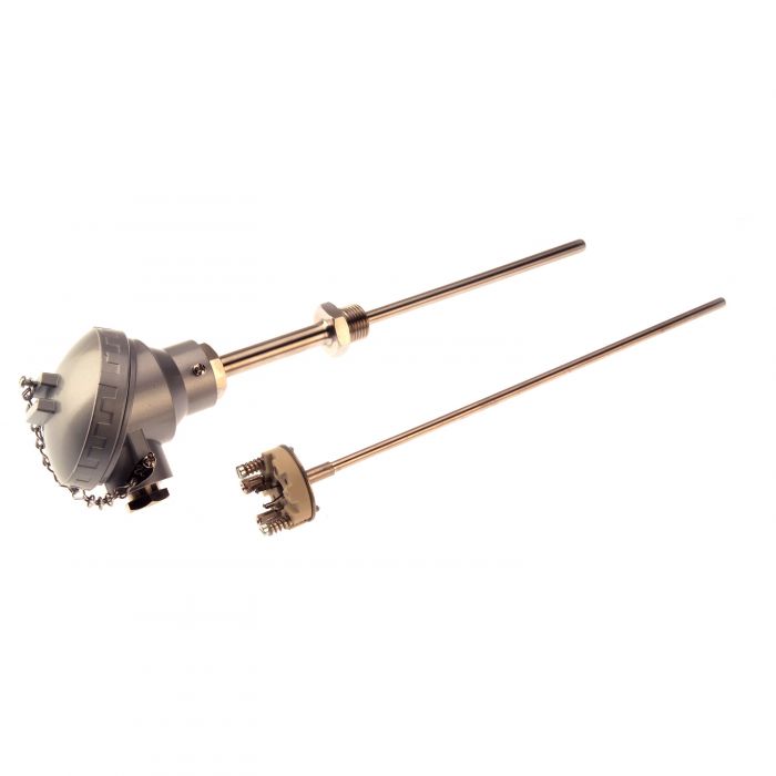
Fig 31: Industrial Probe with Lagging Extension
Installing temperature sensor assemblies into thermowells or directly into the process requires the use of some kind of brass or stainless steel fitting.
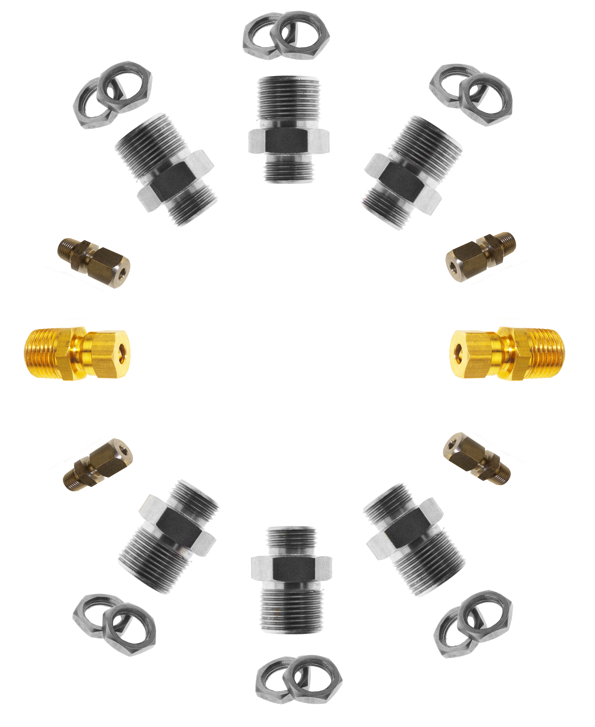
Fig 32: Installation Fittings
Fittings include various threaded unions, bayonet caps (and adapters) and flanges.
Adjustable compression fittings are used directly on probes to achieve the required insertion length in the process and to ensure the proper seating of probes into thermowells.
Adjustable flanges can similarly be used to secure the sensor assembly into the process. Bayonet caps provide a method of quick fitting into suitable adapters located in the process; this technique is widely used in plastics machinery.
Bushes and hexagon plugs are used when adjustment or removal is a lesser consideration.
The choice of fitting may be dictated by the need for pressure integrity or by physical size constraints. Compression fittings and threaded bushes can be supplied with tapered threads to achieve a pressure-tight connection.
Connections between the thermocouple or Pt100 and associated instruments may involve a physical interface with installed wiring and/or sensors. Such interfaces take the form of special connectors, terminal strips, barrier blocks and extension cables.
Due to their location in often adverse environments such as hot working zones of furnaces and machinery, temperature sensors are liable to corrosion and mechanical damage. The need for occasional replacement is inevitable and the use of suitable polarised connectors permits error-free, fast, positive and reliable interchange with no risk of dangerous cross connection.
Plugs and sockets for this purpose are produced to internationally recognised patterns, namely standard (round pin) and miniature (flat pin) versions. Ideally, connectors from the various manufacturers will interconnect directly and be fully compatible; generally, this is achieved. Many variants of the in-line connectors are produced including 3 and 4 pin versions, panel-mounting types and a wide range of multi-way panels and accessories.
Colour coding of the connector bodies is utilised to ensure clear identification of each thermocouple type since the pins and receptacles will normally be of the appropriate thermocouple alloy or compensating material; an international standard IEC584-3 1989, mod. defines these colours for thermocouples. The colour for connector bodies are expected to align with the specified colours but are not expected to be a precise match; such matching is difficult to achieve in mass production mouldings although colours to ANSI/MC96.1 presently dominate the USA markets. The use of the appropriate thermocouple alloys eliminates measurement error due to interconnection via different metals.
The connectors can be mounted directly on to the “cold end” of probes or fitted to extension cables. Good quality products should withstand up to 220°C continuous operation although some manufacturers do not offer such a high temperature rating.
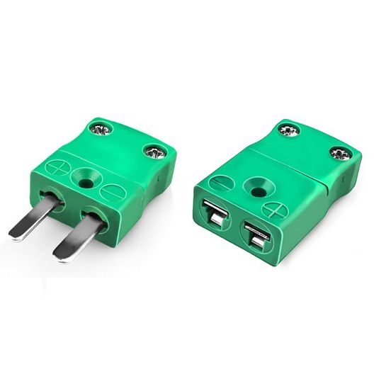
Fig 33: Connectors
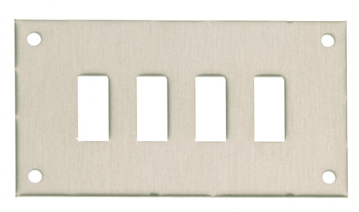
Fig 34: Panel Mounting Connector
Barrier Terminals and DIN style terminal blocks used in DIN pattern heads are also available with colour coded bodies and connections in thermocouple alloys. Their use instead of those with copper or brass connections will result in improved accuracy throughout the thermocouple circuit.
Connectors and terminal blocks are available with copper conductors for use with Pt100 Sensors. Body colours are not subject to any international standard but white is generally used as distinct from the thermocouple colours.
Can’t find what you need? Call or email our technical sales team on
+44 (0) 1243 871 280 or sales@labfacility.com for help with product selection and technical support